Making the wheels spin | Hacking a cleaning Robot
This post is part of a series about hacking and modding a cleaning robot.
Introduction
In my last post (found here) I dove deep into the robot’s PCB and took a look at its features. Here I want to show how I found a way to integrate a microcontroller into the robot PCB and use it to control the wheels.
To achieve this three things were needed:
- Selecting a suitable microcontroller
- Finding a way to power the microcontroller from the robot battery
- Finding a way to inject driving signals into the motor drivers
Choosing a microcontroller
Finding a suitable microcontroller was probably the easiest part. To make the most of the robot, I defined the following requirements:
- As powerful as possible
- Energy efficient (powered from the robot)
- Being able to power it via 5V
- 5V logic (GPIO) voltage
- Integrated FPU and 32bit arithmetics
- As much RAM as possible (at least more than 2kB)
- Any kind of additional connectivity (Wifi, Bluetooth, LoRa, etc…) would be cool
Therefore, an arduino was not an option. While it draws very little power the ATMega328p on the Uno and Nano-Boards is not very powerful and only comes with 2048B of RAM which is definitely not enough.
The next best thing I found was an ESP-32 Wroom Dev Board I had lying around. This microcontroller comes with a 32bit CPU, way more RAM, and fulfils most of the requirements. The only downside was it’s logic voltage level being 3.3V, but this problem was easily fixed using by some cheap logic-level shifters.
Another nice feature of this microcontroller is the built in Wifi and Bluetooth, considering that I wanted to add a bluetooth controller to the project in the future.
Extracting power
To power the microcontroller, I wanted to use the 5V logic voltage of the robot. The corresponding voltage regulator can supply up to 1.5A of current, which is more than enough for the ESP32-Board.
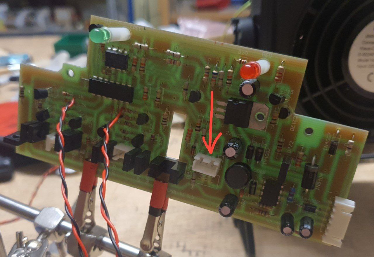
While looking over the robot’s main board, I found two unused spots for JST-Connectors on the circuit board, both of which are connected to GND and 5V. By soldering new headers onto one of them, I got a nice way of powering my external electronics.
Injecting signals into the motor drivers
To use the microcontroller for driving the robot, I had to find a way to connect the ESP32’s GPIO-Pins to the input of the motor drivers. Remembering what I’ve learned from the PCB-Analysis, I figured that the best way to approach this would be to replace the pins 8,9,12 and 13 of the main IC with my own GPIO signals.
My first idea was to cut off the corresponding legs of the main IC and solder the cables to the remaining holes. This turned out to be very hard, since reaching the little legs with even the smallest side-cutters I had was next to impossible, and unsoldering the whole chip would be pretty inconvenient.
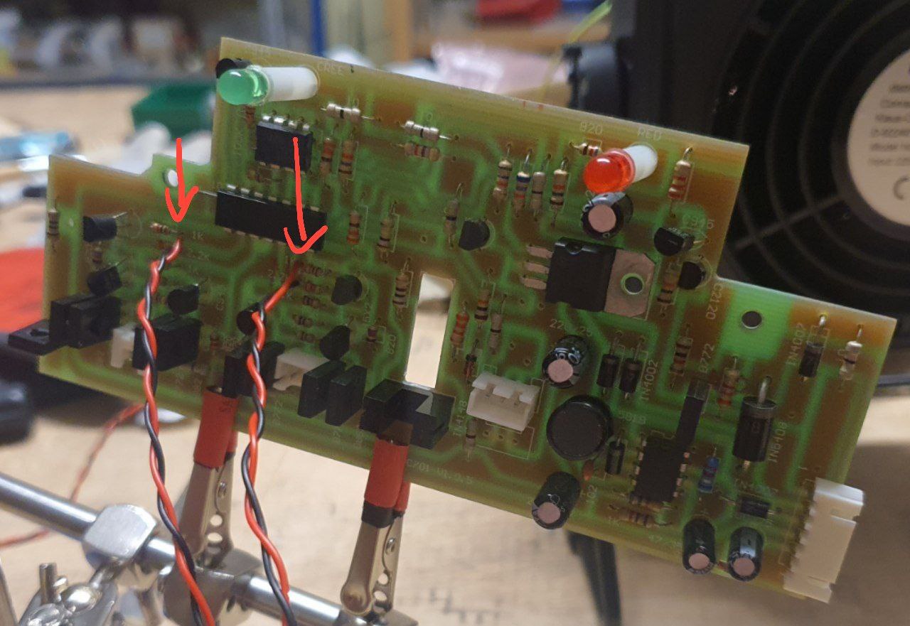
That’s why I a look at the traces of the main IC’s pins again. I found some resistors which seemed to be the input points of the motor drivers and soldered my wires directly to them. To stop the old IC from interfering with my signals, I used a sharp knife to cut the PCB traces at its base.
Testing the connections
To test if everything worked as expected, I wrote a simple script for the ESP32 which turns the connected pins on and of for a certain amount of time. Running this script revealed that everything worked as expected. I could observe the wheels turning and stopping, which meant that my signal injection was a success. I found out that even using PDM-Signals to control the speed of each wheel worked almost flawlessly.