Topan AVC701 PCB Analysis | Hacking a cleaning Robot
Introduction
The other day I got my hands onto a “BRUNEAU TP-AVC701” or “Topan TP-AVC701” cleaning robot and wanted to make it drive autonomously using a Microcontroller. After opening it up and looking at the rather simple PCB, I thought it might be possible to inject signals directly into it, eliminating the need for new motor controllers and a battery charging circuit.
That’s why I analyzed the contents of the PCB and traced all copper lines and parts to its original purpose.
Rainer Rebhan also hacked this robot, if you don’t want to keep the old PCB is suggest checking out his website.
Robot Overview
The robot itself is rather simple. It drives around in fixed patterns, reversing and turning away if it hits something with its front bumper. It is turned on using a switch at the top and can be charged using an external 14.4V Power Supply.
The following images show the robot from the outside and inside:
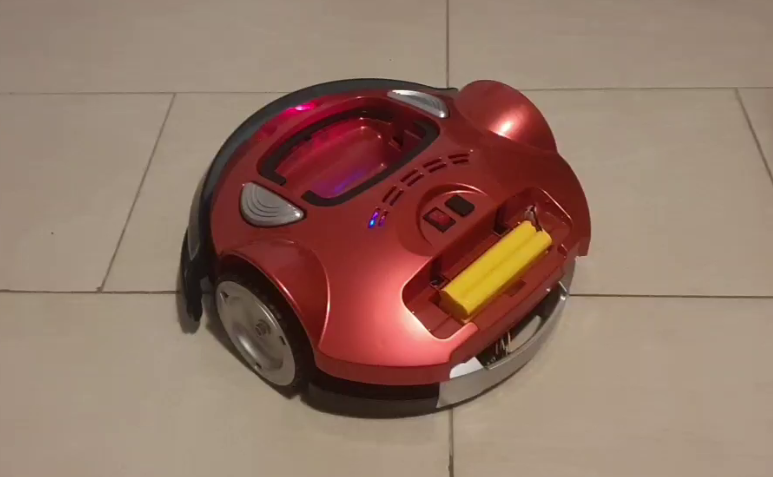
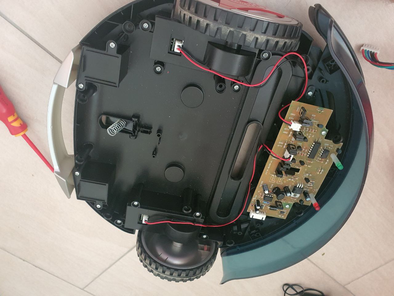
As you can see, there is a lot of space for modifications and tinkering. Note that I already removed some unneeded parts like the vacuum motor.
Main PCB Features
The default PCB already comes with a good set of features, namely:
- Battery Charging/Discharging logic
- Motor Driver for both wheel motors
- On/Off control for the vacuum motor
- Collision Detection using the front bumper
- Two DC/DC Converters
PCB Sections
The following image shows the different purposes I determined for the different areas of the main PCB. Each feature is explained in more detail below.
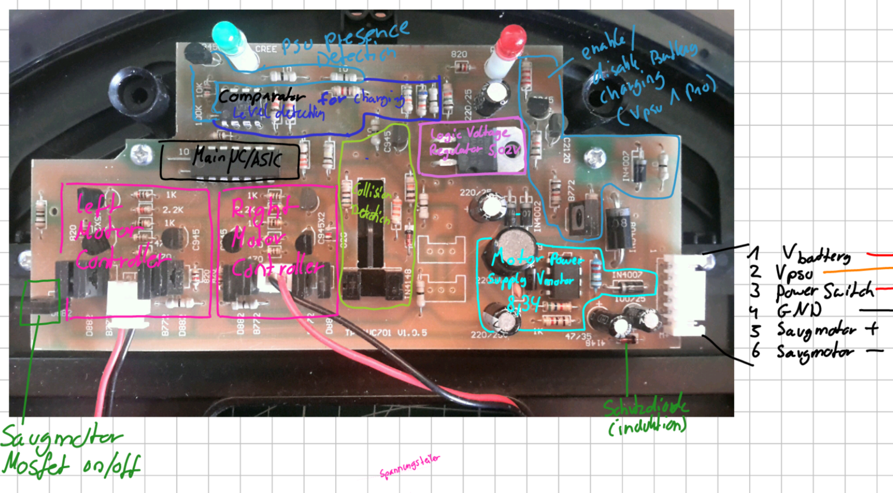
6-Pin Connector
The 6 Pin JST connector on the right side connects the main PCB to two small daughterboards in the casing. These connect to the battery, PSU and ON/OFF switch. It also connects directly to the vacuum motor.
| Pin | Purpose |
|---|---|
| 1 | V_battery (Positive battery terminal) |
| 2 | V_psu (Positive Power supply terminal) |
| 3 | Power Switch (ON: V_battery, OFF: NC) |
| 4 | Ground |
| 5 | Vacuum Motor + |
| 6 | Vacuum Motor - |
Note that the Power Switch at Pin 3 is connected to V_battery if the switch is turned ON. This serves as the main power source for the robot when running. Connector Pin 1 on the other hand is always connected to the Battery and is used to charge the robot when a PSU is present.
Main IC
The main IC seems to be either a microcontroller or (more likely) a custom made ASIC. It controls basically everything on the robot including:
- Both driving Motor’s speed
- Vacuum Motor ON/OFF
- Battery charging
- Blinky LEDs
- Collision Detection
Picture of the main IC:
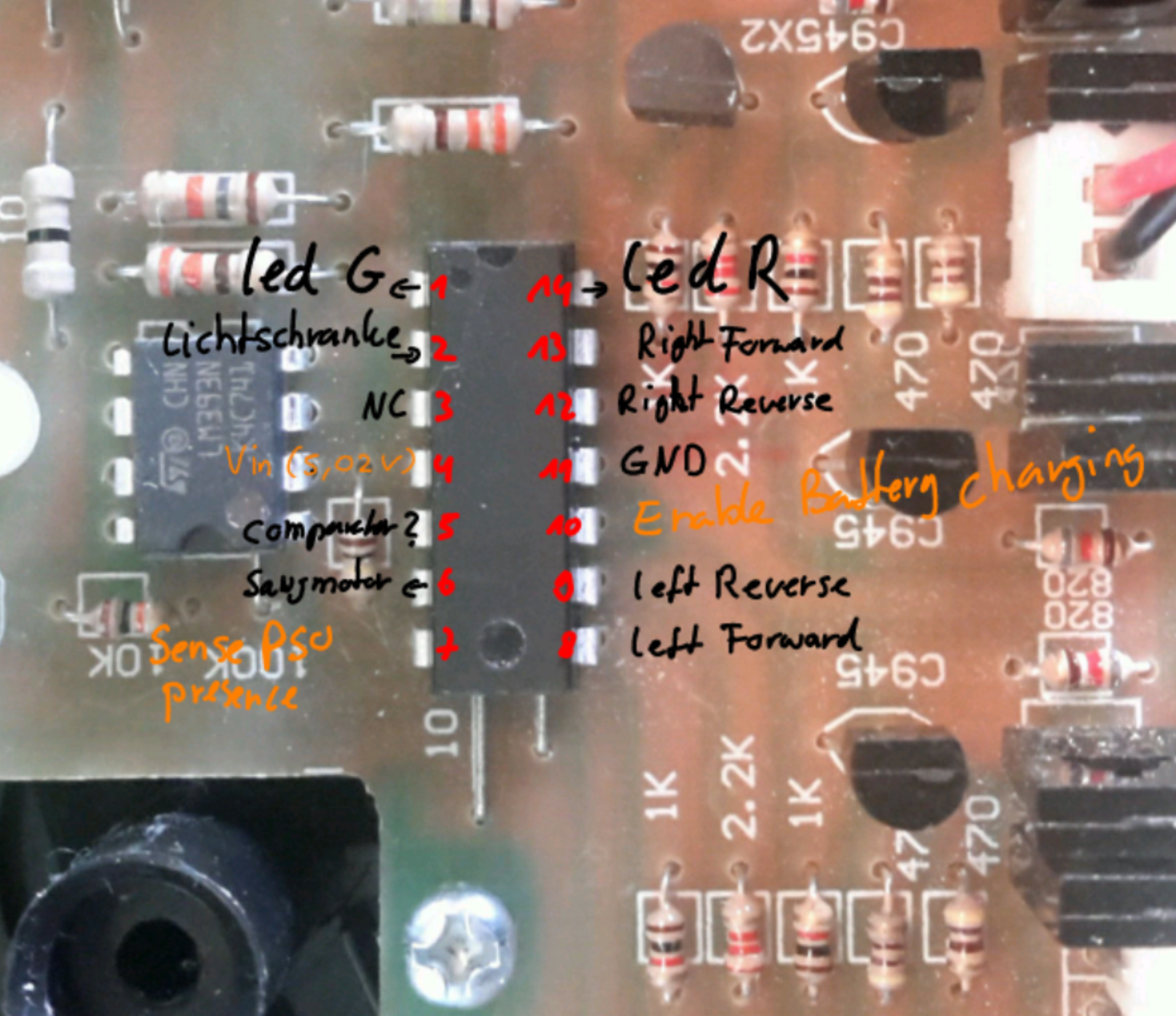
Pinout:
| Mode | Purpose | Pin | Pin | Purpose | Mode | |||||||
|---|---|---|---|---|---|---|---|---|---|---|---|---|
| ┌ | ─ | \_/ | ─ | ┐ | ||||||||
| Output | Green LED | 1 | ─ | ┤ | 0 | ├ | ─ | 14 | Red LED | Output | ||
| Input | Light Barrier | 2 | ─ | ┤ | ├ | ─ | 13 | Right Wheel Forward | Output | |||
| NC | 3 | ─ | ┤ | ├ | ─ | 12 | Right Wheel Reverse | Output | ||||
V_logic (5V) |
4 | ─ | ┤ | ├ | ─ | 11 | Ground | |||||
| Input | Comparator | 5 | ─ | ┤ | ├ | ─ | 10 | Battery Charging Enable | Output | |||
| Output | Vacuum Motor On/OFF | 6 | ─ | ┤ | ├ | ─ | 9 | Left Wheel Reverse | Output | |||
| Input | Sense PSU Presence | 7 | ─ | ┤ | ├ | ─ | 8 | Left Wheel Forward | Output | |||
| └ | ─ | ─ | ─ | ┘ |
Motor Drivers
There are two motor drivers, each consisting of a H-Bridge and some upstream logic.
The following pins from the main IC are used for driving:
| Pin NR | Motor | Purpose |
|---|---|---|
| 13 | Right | Forward |
| 12 | Right | Reverse |
| 9 | Left | Reverse |
| 8 | Left | Forward |
The previously mentioned extra logic makes sure that the robot does not try to drive forward and reverse at the same time:
| Pin 8 | 13 (Forward) | Pin 9 | 12 (Reverse) | Motor Driver Output |
|---|---|---|
| 0 | 0 | Stop |
| 0 | 1 | Reverse |
| 1 | 0 | Forward |
| 1 | 1 | Reverse |
Charging Circuit
The Charging logic consists of a Voltage Sensing Circuit and a Charging Activation Circuit controlled by the main IC.
Using its two internal Comparators, the lm393N checks the reduced PSU/Battery Voltage max(V_battery, V_PSU) and the Motor Voltage V_motor against the 5V logic Voltage V_logic and outputs a logic 1 to the main IC if either of the Voltages is greater than V_logic.
In logic terms, this would be:
out = (V_motor >= V_logic) or (max(V_psu, V_switch) >= V_logic)
Note:
The exact purpose of the Comparator is currently unclear to me. Unfortunately, I don’t have the original PSU anymore and therefore cannot confirm my theories.The measurements using another Power Supply did not replicate my expected behavior so take this section with a grain of salt.
Depending on the logic signal of the comparator (and maybe something else), the main IC enables the battery charging logic, which checks if a PSU is present, and if so, connects V_battery and V_PSU together using a MOSFET.
Light Barrier
The light barrier is used for detecting collisions using the front bumper. If the robot bumps into something while driving, a plastic piece blocks the light barrier and the robot stops, reverses and turns around.
Power Distribution
The PCB has two main Power Sources: The Battery and an external Power Supply. Depending on the power source used, two different DC/DC Converters create the voltages needed by the components and motors.
Here is a quick overview over the different power rails:
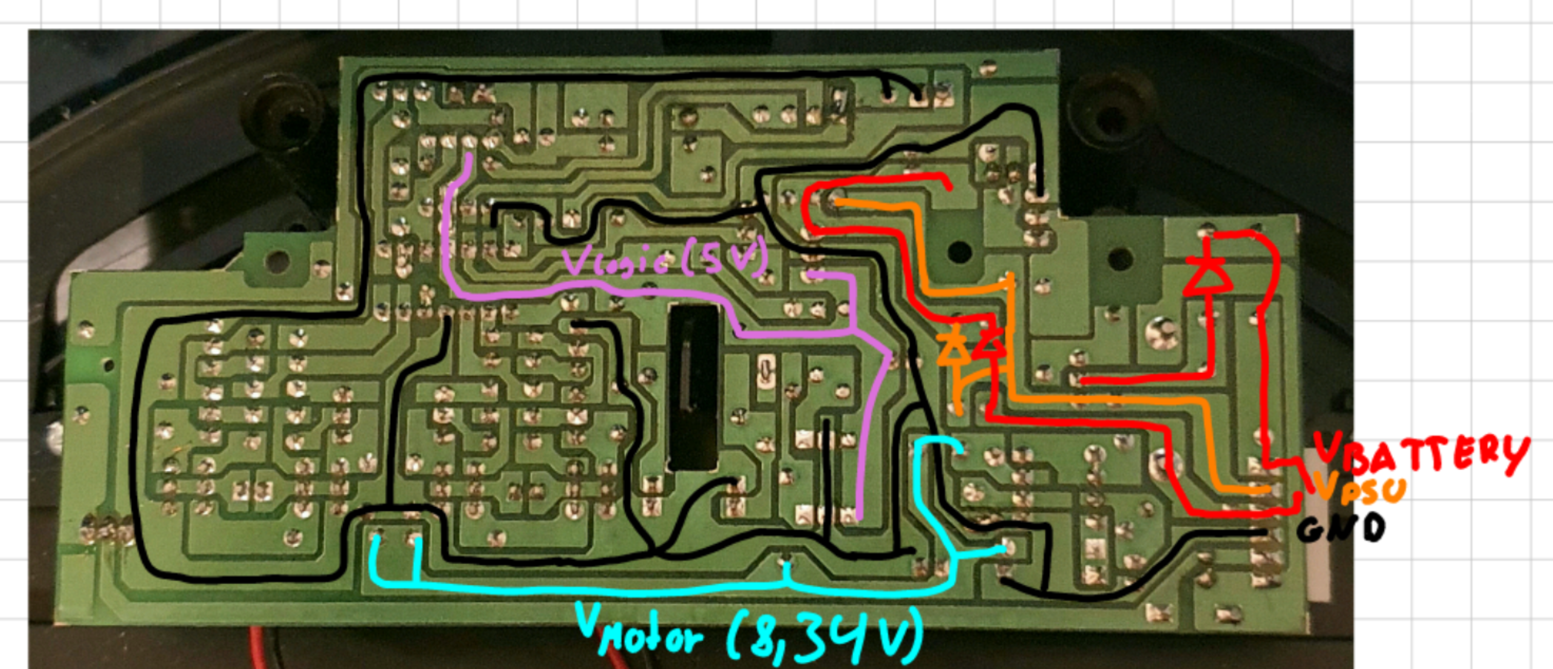 Note that the Image is mirrored to make it easier matching the components on the other side.
L7805CV Voltage Regulator
This Voltage regulator receives the variable voltage from either the Battery or the Power Supply (if connected) and regulates it down to a constant 5.02V. It is used to power the main IC and the light barrier.
According to its data sheet, it has all kinds of protection circuits and can provide up to 1.5A of current (although this requires an additional heat sink).
34063AP1 Buck/Boost Converter
This is the second DC/DC Converter on this board. Its purpose is to provide 8.34V to the motor controller of both driving motors.
It only delivers power when the robot is in battery powered mode and the switch is turned on.
Vacuum Motor
The Vacuum motor is using the battery voltage V_Switch for power. It can be switched ON/OFF by the main IC using a MOSFET. For my purposes it was not needed anymore, which is why I removed it.