Driving Around | Hacking a cleaning Robot
This post is part of a series about hacking and modding a cleaning robot.
Introduction
In my last post I described how I got a microcontroller to interact with the motor drivers on the robots mainboard. After that it was time to actually write some software so that we can use the wheels for more than just driving forward at full speed.
I want to use the robot for more demanding tasks such as automated driving in the future. For this to work, I needed a bigger framework of all kinds of features and functionality, which is why I started to develop Robocore.
The motor driver script
To set the speed and direction of each wheel using a simple function call like:
//drive forward
leftWheel.Drive(speed=255)
I needed some kind of script communicating with the motor drivers on the mainboard.
This would then be helpful for more abstract ways of driving like using inverse kinematics (more on that later).
The task for the motor driver script would be to drive one of the wheels in the following way:
- Drive the motor with a given speed
- Drive in reverse when a negative speed is given
- Be able to drive at slower than full speed (eg. 50% speed)
- Ignore invalid speeds (eg. 200% speed)
- Limit the motor to a minimum speed
- Do all this while using the two-wire signal inputs of the motor drivers on the mainboard
Realizing this was very straight forward. I only needed to provide the PWM-Signals corresponding to a desired speed to the forward or backwards inputs of the motor driver and check if it’s within certain boundaries.
The minimum speed requirement mentioned above was needed since I found out that the motors were actually not turning for PWM-Signals below a certain threshold. This way I can just turn the motors off if such a speed is given, hopefully preventing them from getting fried.
For future use I also added some functions to retrieve the current speed and driving direction from the motor. These might be helpful in the future.
The resulting code can be found in motor_driver.cpp inside my Robocore project. It contains a class representing one single motor and interacts with the corresponding motor controller to provide functions for getting and setting the motor speed.
Inverse Kinematics
Forward Kinematics
In robotics, the (forward) kinematics of a mobile robot usually describe the formulas and equations which tell the robot the speed and trajectory it is driving, given the speed and steering angle of all of its wheels. This obviously depends on the number of wheels, wheel placement, and their respective freedom of movement. Or maybe a robot might not even have wheels, but rather tracks like a tank or legs like a dog.
Inverse Kinematics
In contrast, the inverse kinematics describe the exact opposite. They are used to calculate how the robot needs to turn its wheels in order to drive on a given trajectory. This again heavily depends on the robots wheel configuration.
This is exactly what I needed to drive my robot around later when using mapping and autonomous navigation. Luckily, my robot has only two wheels, each of them being opposite of each other. Both wheels are only able to turn forward or backwards. Such a wheel configuration is called a “differential drive” since the difference in speed of both wheels determine if and how much the robot is turning.
There are many resources on the internet describing differential drive kinematics, but just copying and pasting formulas is boring :) That’s why I decided to do a little math myself and derived the inverse kinematics by hand. This way I also got full control on the details and knew what to do when implementing them into my Robocore project.
Deriving Differential Drive Inverse Kinematics
In the beginning, I first had to actually specify how I wanted the kinematics to work. Depending on the robot and use case, the details here might differ from implementation to implementation.
My first Idea was to give the robot a trajectory as a circle radius and the driving speed. This way the robot would set the speed of its wheels to follow this given circle.
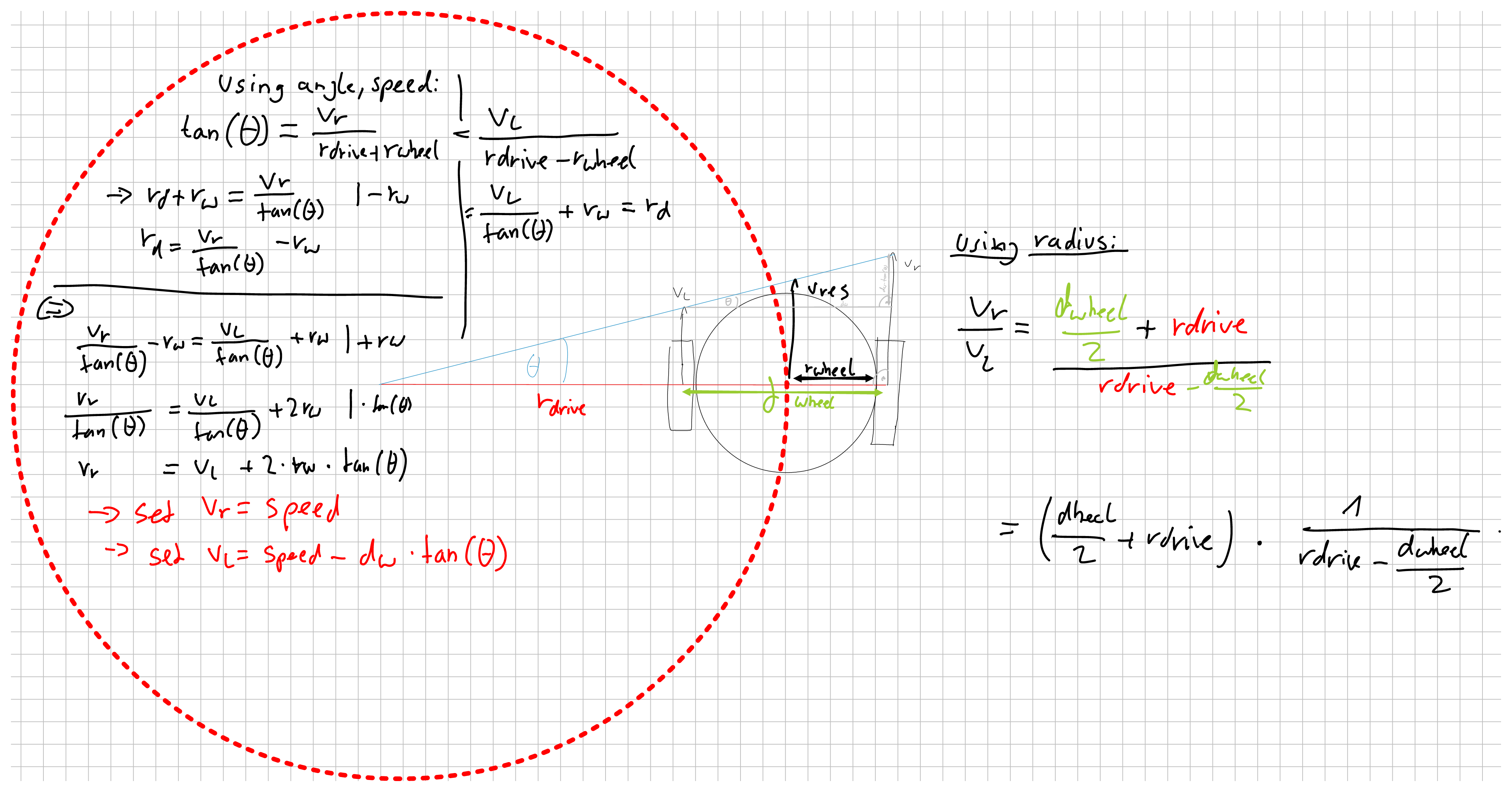
This approach however turned out to be unfitting for my purposes for the following reasons:
-
Two of the most common movements require ugly edge cases. Driving straight forward requires the radius to be infinitely large and turning on the spot would need a radius of 0. Both of these cases are difficult to represent and have to be checked manually.
-
Always giving a robot a circular trajectory might not be very useful for other tasks. Navigation for example would require some extra maths just to calculate a circular trajectory if we want to drive to a point in worldspace (This wouldn’t even be the shortest path for a differential drive robot).
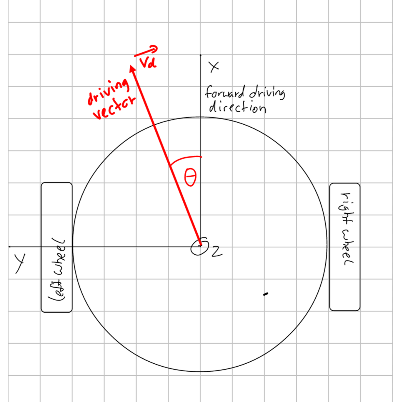
Therefore, I found another way to tell the robot where to go, using a rotation angle and the desired speed. The idea behind that is that I later could create a vector from the robots position to the desired goal point, calculate its angle with respect to the robot, and use this information to tell the robot how to turn.
To achieve this, the robot should have the following behavior:
| Input Angle (deg | rad) | Left Wheel Speed | Right Wheel Speed | Resulting action |
|---|---|---|---|
| 0° | 0 | 100% | 100% | Drive straight forward |
| 45° | pi/4 | 0% | 100% | Drive a counterclockwise circle around the left wheel |
| 90° | 2*pi/4 | -100% | 100% | Turn counterclockwise on the spot |
| 135° | 3*pi/4 | -100% | 0% | Drive a counterclockwise circle around the right wheel (backwards) |
| 180° | 4*pi/4 | -100% | -100% | Drive straight backwards |
| 225° | 5*pi/4 | 0% | -100% | Drive a clockwise circle around the left wheel (backwards) |
| 270° | 6*pi/4 | 100% | 0% | Turn clockwise on the spot |
| 315° | 7*pi/4 | 100% | 100% | Drive a clockwise circle around the right wheel |
In between each edge case the speed of one wheel should stay at 100% while the other wheels speed increases / decreases linearly.
Visually, this would look somewhat like this:
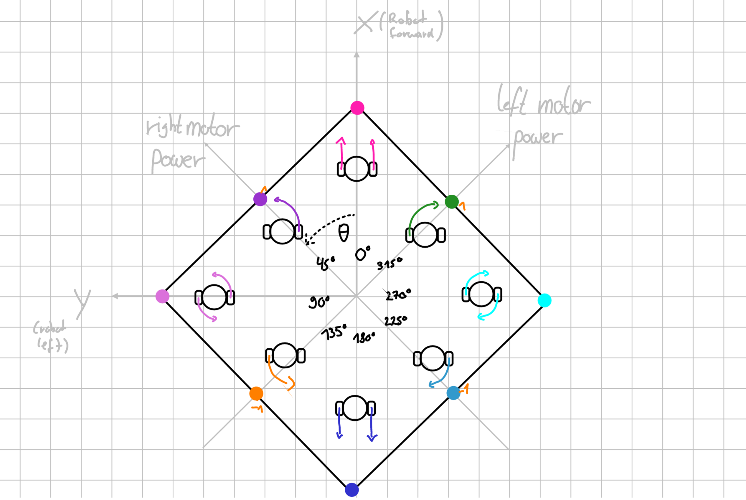
Here, the rectangle seen represents a function of the angle which returns the speed of the wheels. Note that the axes for the wheel speeds are rotated by 45° with respect to the direction the robot itself is facing (x-axis).
To derive said rectangular function, we divided the mentioned edge cases into four sections where one wheel remains with constant speed. For the non-constant speed of the other wheel, we used simple trigonometry, namely tangens, to get the speed percentages for each angle.
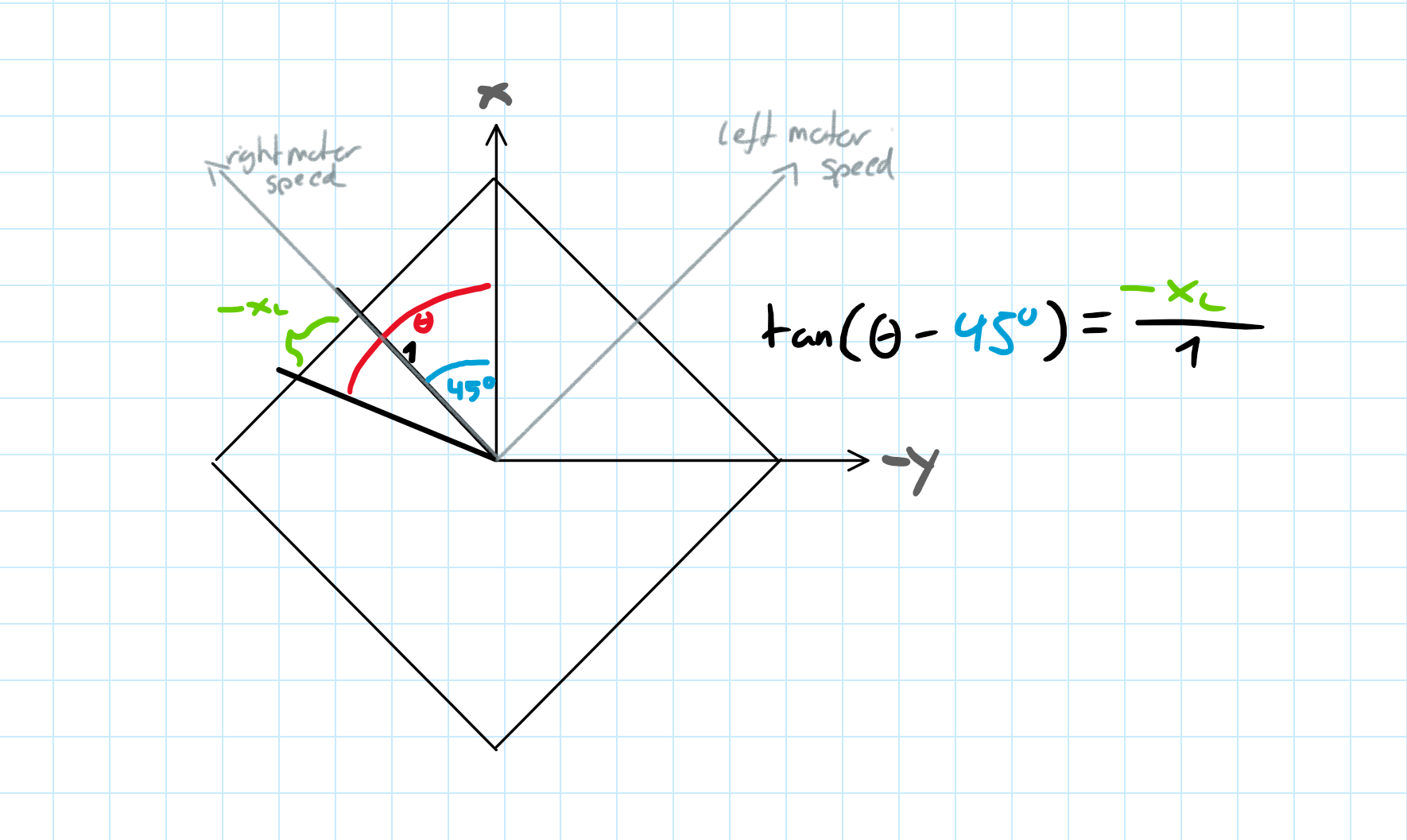
This resulted in the following inverse kinematics:
| Start to end Angle Theta (deg | rad) | x_l (left wheel speed) | x_r (right wheel speed) |
|---|---|---|
| (0°-90° | 0-pi/2) | tan(pi/4 - Theta) | 1 |
| (90°-180° | pi/2-pi) | -1 | tan(3*pi/4 - Theta) |
| (180°-270° | pi-1.5*pi) | tan(Theta - 5*pi/4) | -1 |
| (270°-360° | 1.5pi-2pi) | 1 | tan(Theta - 7*pi/4) |
This inverse kinematic function was then implemented into Robocore inside differential_drive.cpp as function DifferentialDriveInverseKinematics(double angle) and then combined with the motor driver software to set the speed of the robots wheels. This now made me able to easily control the robot by specifying a speed and trajectory angle.