Jekyll2026-03-20T13:38:28+00:00https://skyfighter64.github.io/feed.xmlSkyfighter64’s Home PageDiscover updates and summaries for some of my latest projects and ideas.Introduction to ALUP2026-03-01T13:53:33+00:002026-03-01T13:53:33+00:00https://skyfighter64.github.io/2026/03/01/Introduction-To-ALUPWhat it’s all about
Many people know traditional LED strips, where you can change the color of all LEDs using a small Remote. For Addressable LED strips however, you get the possibility to change the color of every LED individually. To control the color of each LED however, one often either uses some kind of Controller which only has some preprogrammed patterns, or a microcontroller which needs to be programmed manually and is limited in its performance and features.
But what if I want to do MORE than this?
What if I would like to use the computational power, connectivity and flexibility of a PC, Laptop, or other device?
This is where ALUP comes in.
ALUP builds the bridge between the LEDs and a powerful Computer by using a Microcontroller to “translate” instructions Between Computer and LEDs.
More Specifically, it defines how the Computer and the Microcontroller have to communicate in order to successfully transfer commands directly to the LEDs.
This makes it possible for the computer to “tell” the LED strip things like:
“I want LED 5 to be Red”
“Make all LEDs go dark”
“The LEDs 5, 6 and 9 should switch to green in 1 second from now”
By making this kind of communication possible, a whole new world of possibilities opens up. Users can now use the power of their computer for example to:
Create complex music visualization with lots of audio processing
Synchronize multiple LED-Strips to show the same things at exactly the same time
Light up their room depending on images shown on their computer screen
Create light shows based on music videos
and so much more.
Where to learn more
If you are interested in this project, I suggest checking out more posts here:
Python-ALUP - Python Reference Implementation for an ALUP Sender
Arduino-ALUP - Reference Implementation for an ALUP Receiver using the Arduino Framework
ALUP-Controller - Feature-Rich Command Line tool for interacting with an ALUP-Receiver
ALUP-Lightshow - Create time stamp-based light shows using ALUP
Audio-Visualizer - Python-Based Audio Visualizer for Addressable LEDs on Raspberry Pi using CAVA
]]>Time Synchronization for the ALUP Protocol2025-09-09T22:14:49+00:002025-09-09T22:14:49+00:00https://skyfighter64.github.io/timesync/2025/09/09/Time-SynchronizationThis post is part of a series about my ALUP Protocol side project.
Introduction
The ‘ALUP’ is an application layer protocol to communicate RGB-Data from a PC to a Microcontroller in order to light up addressable LED strips from devices with more computing power than an Arduino.
Originally it was only intended for the use with one single ALUP Receiver, but more recently I figured that it would be useful if multiple Receivers could be grouped together to update their LEDs synchronously. More specifically, I wanted to add timestamps to each Data Frame, which then tells the Microcontroller when exactly to update the LEDs. This requires time synchronization for both devices.
Background
A computer usually synchronizes it’s local time with accurate time servers over the internet. This makes its internal timekeeping sufficiently exact for everyday use. Most Microcontrollers however do not support this feature and are often not even connected to the internet at all. For them, time tracking is done by an internal timer which starts at 0 when they first boot up.
These cheap internal timers are often prone to some drift, where the internal clock counts either slightly faster or slower than the real time (usually ~ $3-4 \frac{s}{day}$).
<!—
In order to synchronize the time between a PC and a Microcontroller, we need to:
Calculate the Offset of the Microcontroller’s clock to the real time
Update the offset often to minimize the inaccuracy through drift
Integrate it into the existing protocol
Make it work efficiently
–>
The generic Precision Time Protocol’s Synchronization Mechanism
About half a year ago I was first introduced to the time synchronization mechanism of the generic Precision Time Protocol in university. It was fascinating for me how simple it was and how well it worked once I understood the principle behind it.
The setup is similar to our Microcontroller situation: A Master device which has the accurate time (master time domain), and a Slave device which has its own local time (slave time domain) synchronize their time using time measurements.
How it works:
The master device sends its accurate time $T$ to the slave. Because of the unknown transmission delay ( 10-100ms or more), the received time $T$ is outdated once it reaches the slave. For this reason, the Master notes the time it sent out the packet ($t_1$) and the sender notes the time it received the packet ($t_2$).
The master transfers $t_1$ to the Slave in a follow up packet.
The slave sends a packet to the master and notes the sending time $t_3$.
The master notes the receiving time $t_4$ and responds to the delay packet by sending $t_4$ to the slave.
The slave now has all time stamps $t_1, t_2, t_3, t_4$ and can calculate the transmission delay $\Delta_t$:
\[\Delta_t = \frac{(t_2-t_1) + (t_4-t_3)}{2}\]
With this, he can correct the previously exchanged Time $T$:
\[T_{corrected} = T + \Delta_t\]
Assumptions and Caveats
This method of time-correction makes some non-trivial assumptions:
There should be no clock drift on either side
Transmission latency of $T$ needs to be the the same as $\Delta_t$
Which implies that:
Sending and receiving latencies are the same (symmetric)
Sending latency and $T$’s transmission latency are the same
These assumptions are the source of error in practical applications. Especially when working with wireless connections, the latency spikes caused by the layer 1 backoff-algorithms, like CSMA/CA in WiFi, can lead to inaccuracies. For this reason, we found that it is good practice to make multiple time synchronizations and take the median as a final result.
To reduce the impact of time drift, it is furthermore recommend to frequently repeat the synchronization Algorithm as often as needed.
Some further Notes:
In conclusion, all that is done is:
Transmit the accurate time $T$ from the master to the slave
Measure the transmission delay and correct $T$ on the slave
Simple, right?
Also, one might think: “If the sending and receiving latencies need to be symmetric, why do we measure both and not only the sending latency?”.
It’s because we actually need the measurement in both directions due to the of the different time domains on the master and slave before synchronization (aka. we need to consider which clock measured which time).
We can’t just subtract $t_2$ and $t_1$ because $t_1$ is in the master time domain and $t_2$ is in the slave time domain (The same goes for $t_4$ and $t_3$).
However, subtracting $t_4$ and $t_1$ as well as $t_3$ and $t_2$ is entirely valid, because the first two were both measured by the master’s clock and the second two by the slave’s. Calculating their difference therefore works just fine and eliminates the constant offset so we can calculate the average.
In formulas, it therefore would make more sense to rewrite:
\[\Delta_t = \frac{(t_2-t_1) + (t_4-t_3)}{2}\]
as:
\[\Delta_t = \frac{(t_4-t_1)-(t_3-t_2)}{2}\]
Adaptation for ALUP
With the ALUP being structured very differently, we made some adaptations in order for this mechanism to work:
The protocol has only two communication steps (see ALUP Docs), therefore, we don’t want to do the 4-step handshake from gPTP but rather simplify it to two steps.
ALUP tries to put as much work on the Sender (gPTPs Master) as possible, therefore we want to track both times on the Sender instead of telling the Receiver (Slave) to correct its own time.
So the overall goals are:
Synchronize the Receiver time as often as possible
Reduce the four steps from gPTP to only two
Make the Sender (Master) keep the times instead of the Receiver (Slave)
For this, we needed to turn around the gPTP’s mechanism so that the Sender (Master) has $t_1,t_2,t_3,t_4$ in the end. This step also already reduces the communication effort from 4 step to only two (yay :>).
The new communication diagram looks something like this:
The simplified time synchronization graph
With:
\[\Delta_t = \frac{(t_2-t_1) + (t_4-t_3)}{2}\]
The delta is still calculated in the same way as before, but you may notice that we do not send $T$ over to the Sender. This is because we don’t need a specific time from the Sender it but can rather use any other time such as $t_3$ for a replacement. This simplifies the communication further
from:
\[T_{Receiver} = T + \Delta_t\]
to:
\[T_{Receiver} = t_3 + \Delta_t\]
Therefore, we now got the receiver’s local time $T_{Receiver}$ successfully from the receiver to the sender with minimal error thanks to $\Delta_t$.
Since it is more practical, instead of storing $T_{Receiver}$ we rather store the offset for the Receiver’s time to the Sender’s time $\delta^S_R$:
\[\delta^S_R = T_{Receiver} - T_{Sender}\]
Note: For $\delta^S_R$, the $S$ and $R$ denote that this is the offset of the Sender’s time and the Receiver’s time.
This way, we don’t need to track the Receiver’s time on the Sender separately, but can instead use the Sender’s system time at any point to calculate the corresponding local time on the Receiver by using:
\[T_{Receiver} = T_{Sender} + \delta^S_R\]
The last simplification we do is to choose the measuring point for $T_{Sender}$ smartly. To be more specific, we choose $T_{Sender}$ to be the same as $t_4$.
Simplification of the formula
From before, we found the following formulas:
$\Delta_t = \frac{(t_2-t_1) + (t_4-t_3)}{2}$
$T_{Receiver} = t_3 + \Delta_t$
$\delta^S_R = T_{Receiver} - T_{Sender} $
$T_{sender} = t_4$
We combine and simplify them with respect to $\delta^S_R$ in order to get one singular formula which is simpler to write and easier to calculate:
Start with:
\[\delta^S_R = T_{Receiver} - T_{Sender}\]
Put in $T_{Receiver} = t_3 + \Delta_t$:
\[\delta^S_R = (t_3 + \Delta_t) - T_{Sender}\]
Put in $T_{Sender} = t_4$:
\[\delta^S_R = (t_3 + \Delta_t) - t_4\]
Put in $\Delta_t = \frac{(t_2-t_1) + (t_4-t_3)}{2}$:
This formula can calculate the offset from the Receiver’s time to the Senders Time very accurately. We can use it to get the Receiver’s local time from the Sender’s local time very accurately:
\[T_{Receiver} = T_{Sender} + \delta^S_R\]
Note though that the caveats and assumptions from gPTP still apply, therefore:
Timer drift is not considered -> synchronize time often (We do it with every packet)
Synchronization error increases if the sending and receiving latency are not the same -> Collect multiple time synchronizations and use a running median.
Closing words
Now you know in detail how the ALUP time synchronization works and how it was deducted.
In the future, we can use this synchronized time to coordinate the RGB-Colors of multiple Receivers so they can update their LEDs at the same time. Furthermore we can minimize latency and jitter using time stamps in every ALUP Frame.
For reference implementations, see Python-ALUP (Sender) and Arduino-Alup (Receiver). The ALUP Protocol Documentation can be found here.
]]>Driving Around | Hacking a cleaning Robot2024-10-21T21:51:33+00:002024-10-21T21:51:33+00:00https://skyfighter64.github.io/robot/2024/10/21/Driving-AroundThis post is part of a series about hacking and modding a cleaning robot.
Introduction
In my last post I described how I got a microcontroller to interact with the motor drivers on the robots mainboard. After that it was time to actually write some software so that we can use the wheels for more than just driving forward at full speed.
I want to use the robot for more demanding tasks such as automated driving in the future. For this to work, I needed a bigger framework of all kinds of features and functionality, which is why I started to develop Robocore.
The motor driver script
To set the speed and direction of each wheel using a simple function call like:
//drive forwardleftWheel.Drive(speed=255)
I needed some kind of script communicating with the motor drivers on the mainboard.
This would then be helpful for more abstract ways of driving like using inverse kinematics (more on that later).
The task for the motor driver script would be to drive one of the wheels in the following way:
Drive the motor with a given speed
Drive in reverse when a negative speed is given
Be able to drive at slower than full speed (eg. 50% speed)
Ignore invalid speeds (eg. 200% speed)
Limit the motor to a minimum speed
Do all this while using the two-wire signal inputs of the motor drivers on the mainboard
Realizing this was very straight forward. I only needed to provide the PWM-Signals corresponding to a desired speed to the forward or backwards inputs of the motor driver and check if it’s within certain boundaries.
The minimum speed requirement mentioned above was needed since I found out that the motors were actually not turning for PWM-Signals below a certain threshold. This way I can just turn the motors off if such a speed is given, hopefully preventing them from getting fried.
For future use I also added some functions to retrieve the current speed and driving direction from the motor. These might be helpful in the future.
The resulting code can be found in motor_driver.cpp inside my Robocore project. It contains a class representing one single motor and interacts with the corresponding motor controller to provide functions for getting and setting the motor speed.
Inverse Kinematics
Forward Kinematics
In robotics, the (forward) kinematics of a mobile robot usually describe the formulas and equations which tell the robot the speed and trajectory it is driving, given the speed and steering angle of all of its wheels. This obviously depends on the number of wheels, wheel placement, and their respective freedom of movement. Or maybe a robot might not even have wheels, but rather tracks like a tank or legs like a dog.
Inverse Kinematics
In contrast, the inverse kinematics describe the exact opposite. They are used to calculate how the robot needs to turn its wheels in order to drive on a given trajectory. This again heavily depends on the robots wheel configuration.
This is exactly what I needed to drive my robot around later when using mapping and autonomous navigation.
Luckily, my robot has only two wheels, each of them being opposite of each other. Both wheels are only able to turn forward or backwards. Such a wheel configuration is called a “differential drive” since the difference in speed of both wheels determine if and how much the robot is turning.
Rough sketch of the top view of a differential drive robot
There are many resources on the internet describing differential drive kinematics, but just copying and pasting formulas is boring :)
That’s why I decided to do a little math myself and derived the inverse kinematics by hand. This way I also got full control on the details
and knew what to do when implementing them into my Robocore project.
Deriving Differential Drive Inverse Kinematics
In the beginning, I first had to actually specify how I wanted the kinematics to work. Depending on the robot and use case, the details here might differ from implementation to implementation.
My first Idea was to give the robot a trajectory as a circle radius and the driving speed. This way the robot would set the speed of its wheels to follow this given circle.
Robot driving on circle trajectory
This approach however turned out to be unfitting for my purposes for the following reasons:
Two of the most common movements require ugly edge cases.
Driving straight forward requires the radius to be infinitely large and turning on the spot would need a radius of 0.
Both of these cases are difficult to represent and have to be checked manually.
Always giving a robot a circular trajectory might not be very useful for other tasks. Navigation for example would require some extra maths just to calculate a circular trajectory if we want to drive to a point in worldspace (This wouldn’t even be the shortest path for a differential drive robot).
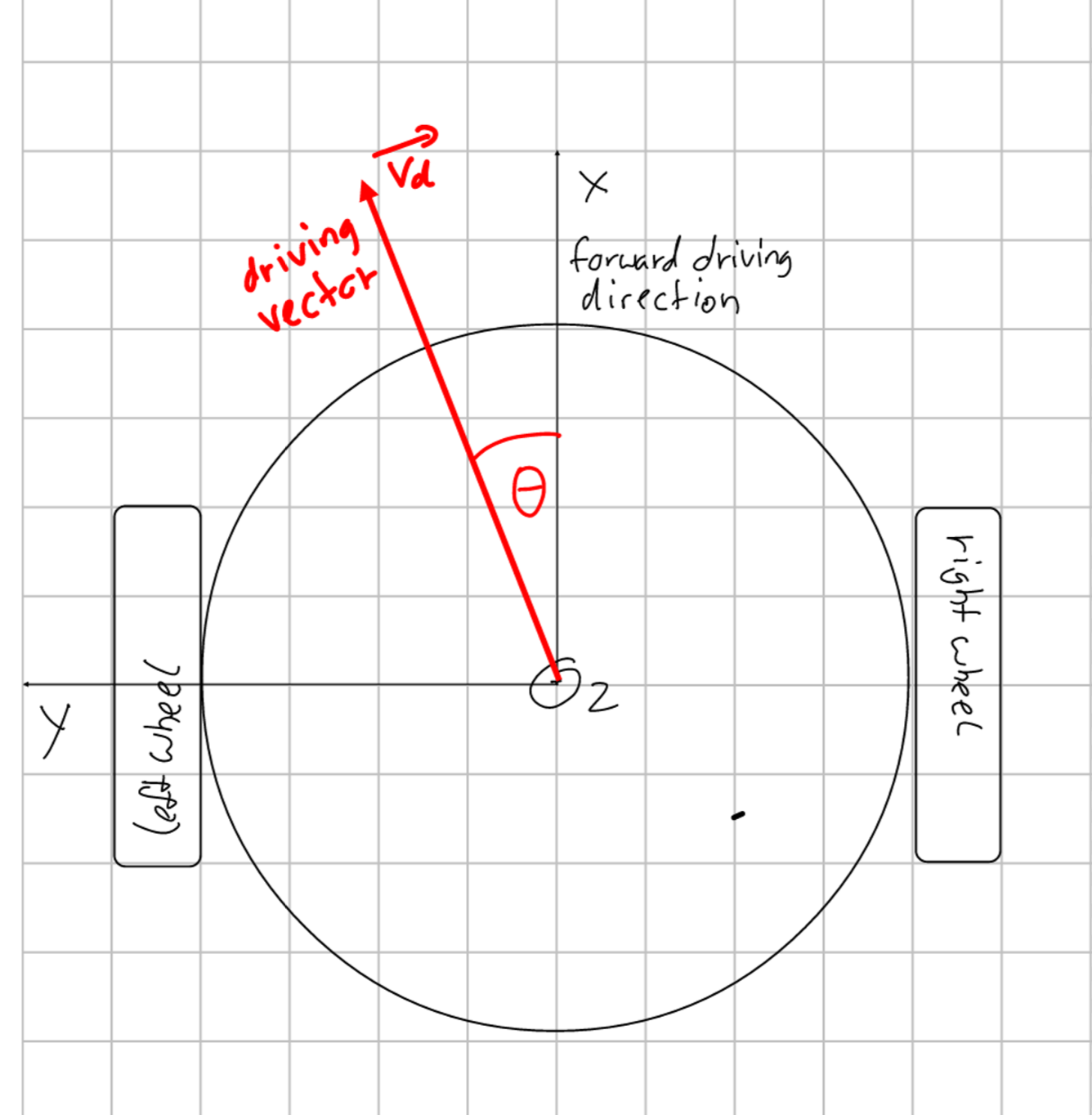
Therefore, I found another way to tell the robot where to go, using a rotation angle and the desired speed.
The idea behind that is that I later could create a vector from the robots position to the desired goal point, calculate its angle with respect to the robot, and use this information to tell the robot how to turn.
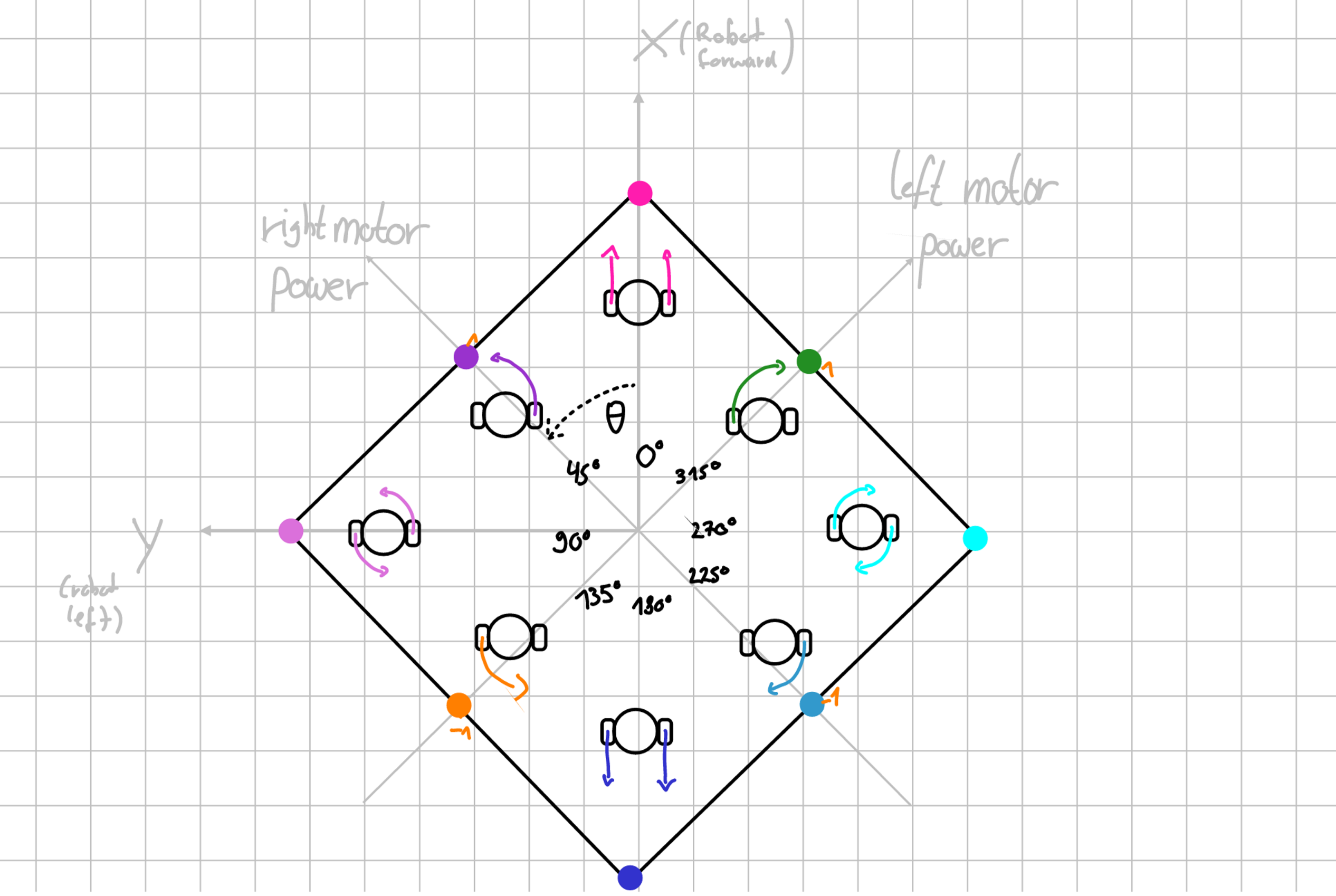
To achieve this, the robot should have the following behavior:
Input Angle (deg | rad)
Left Wheel Speed
Right Wheel Speed
Resulting action
0° | 0
100%
100%
Drive straight forward
45° | pi/4
0%
100%
Drive a counterclockwise circle around the left wheel
90° | 2*pi/4
-100%
100%
Turn counterclockwise on the spot
135° | 3*pi/4
-100%
0%
Drive a counterclockwise circle around the right wheel (backwards)
180° | 4*pi/4
-100%
-100%
Drive straight backwards
225° | 5*pi/4
0%
-100%
Drive a clockwise circle around the left wheel (backwards)
270° | 6*pi/4
100%
0%
Turn clockwise on the spot
315° | 7*pi/4
100%
100%
Drive a clockwise circle around the right wheel
In between each edge case the speed of one wheel should stay at 100% while the other wheels speed increases / decreases linearly.
Visually, this would look somewhat like this:
Visualization of the driving angle edge cases and the corresponding trajectory
Here, the rectangle seen represents a function of the angle which returns the speed of the wheels. Note that the axes for the wheel speeds are rotated by 45° with respect to the direction the robot itself is facing (x-axis).
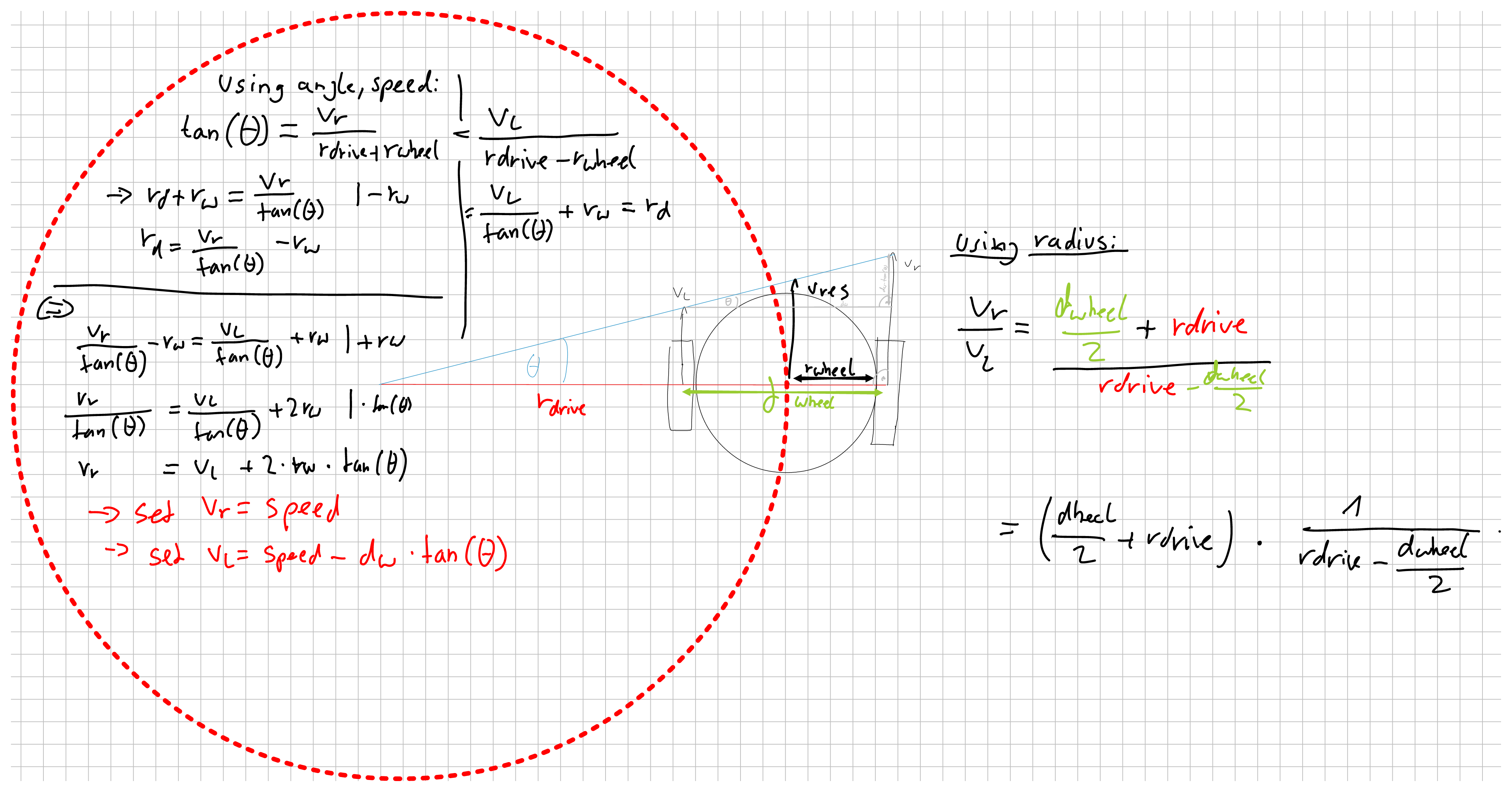
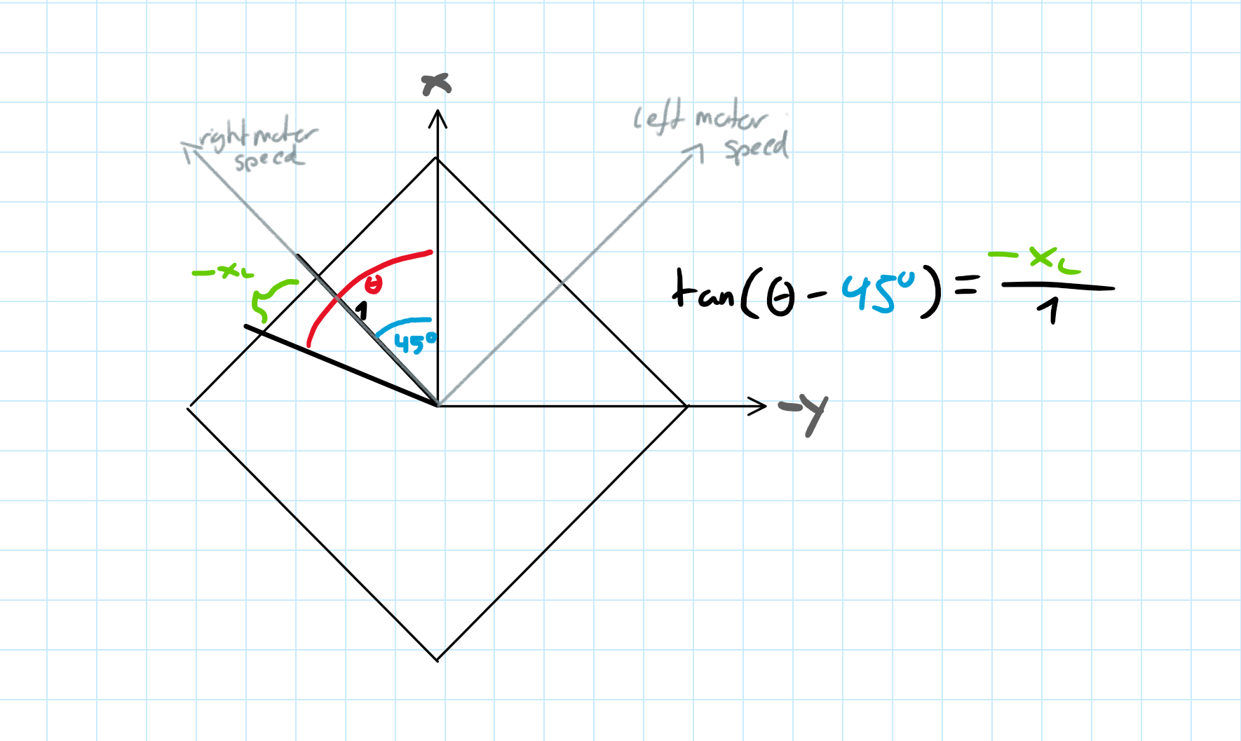
To derive said rectangular function, we divided the mentioned edge cases into four sections where one wheel remains with constant speed.
For the non-constant speed of the other wheel, we used simple trigonometry, namely tangens, to get the speed percentages for each angle.
Example for the trigonometry for one of the four sections
This resulted in the following inverse kinematics:
Start to end Angle Theta (deg | rad)
x_l (left wheel speed)
x_r (right wheel speed)
(0°-90° | 0-pi/2)
tan(pi/4 - Theta)
1
(90°-180° | pi/2-pi)
-1
tan(3*pi/4 - Theta)
(180°-270° | pi-1.5*pi)
tan(Theta - 5*pi/4)
-1
(270°-360° | 1.5pi-2pi)
1
tan(Theta - 7*pi/4)
This inverse kinematic function was then implemented into Robocore inside differential_drive.cpp as function DifferentialDriveInverseKinematics(double angle) and then combined with the motor driver software to set the speed of the robots wheels. This now made me able to easily control the robot by specifying a speed and trajectory angle.
]]>Making the wheels spin | Hacking a cleaning Robot2024-10-19T22:00:33+00:002024-10-19T22:00:33+00:00https://skyfighter64.github.io/robot/2024/10/19/Making-The-Wheels-SpinThis post is part of a series about hacking and modding a cleaning robot.
Introduction
In my last post (found here) I dove deep into the robot’s PCB and took a look at its features. Here I want to show how I found a way to integrate a microcontroller into the robot PCB and use it to control the wheels.
To achieve this three things were needed:
Selecting a suitable microcontroller
Finding a way to power the microcontroller from the robot battery
Finding a way to inject driving signals into the motor drivers
Choosing a microcontroller
Finding a suitable microcontroller was probably the easiest part. To make the most of the robot, I defined the following requirements:
As powerful as possible
Energy efficient (powered from the robot)
Being able to power it via 5V
5V logic (GPIO) voltage
Integrated FPU and 32bit arithmetics
As much RAM as possible (at least more than 2kB)
Any kind of additional connectivity (Wifi, Bluetooth, LoRa, etc…) would be cool
Therefore, an arduino was not an option. While it draws very little power the ATMega328p on the Uno and Nano-Boards is not very powerful and only comes with 2048B of RAM which is definitely not enough.
The next best thing I found was an ESP-32 Wroom Dev Board I had lying around. This microcontroller comes with a 32bit CPU, way more RAM, and fulfils most of the requirements.
The only downside was it’s logic voltage level being 3.3V, but this problem was easily fixed using by some cheap logic-level shifters.
Another nice feature of this microcontroller is the built in Wifi and Bluetooth, considering that I wanted to add a bluetooth controller to the project in the future.
Extracting power
To power the microcontroller, I wanted to use the 5V logic voltage of the robot. The corresponding voltage regulator can supply up to 1.5A of current, which is more than enough for the ESP32-Board.
While looking over the robot’s main board, I found two unused spots for JST-Connectors on the circuit board, both of which are connected to GND and 5V. By soldering new headers onto one of them, I got a nice way of powering my external electronics.
The newly soldered JST-Header
Injecting signals into the motor drivers
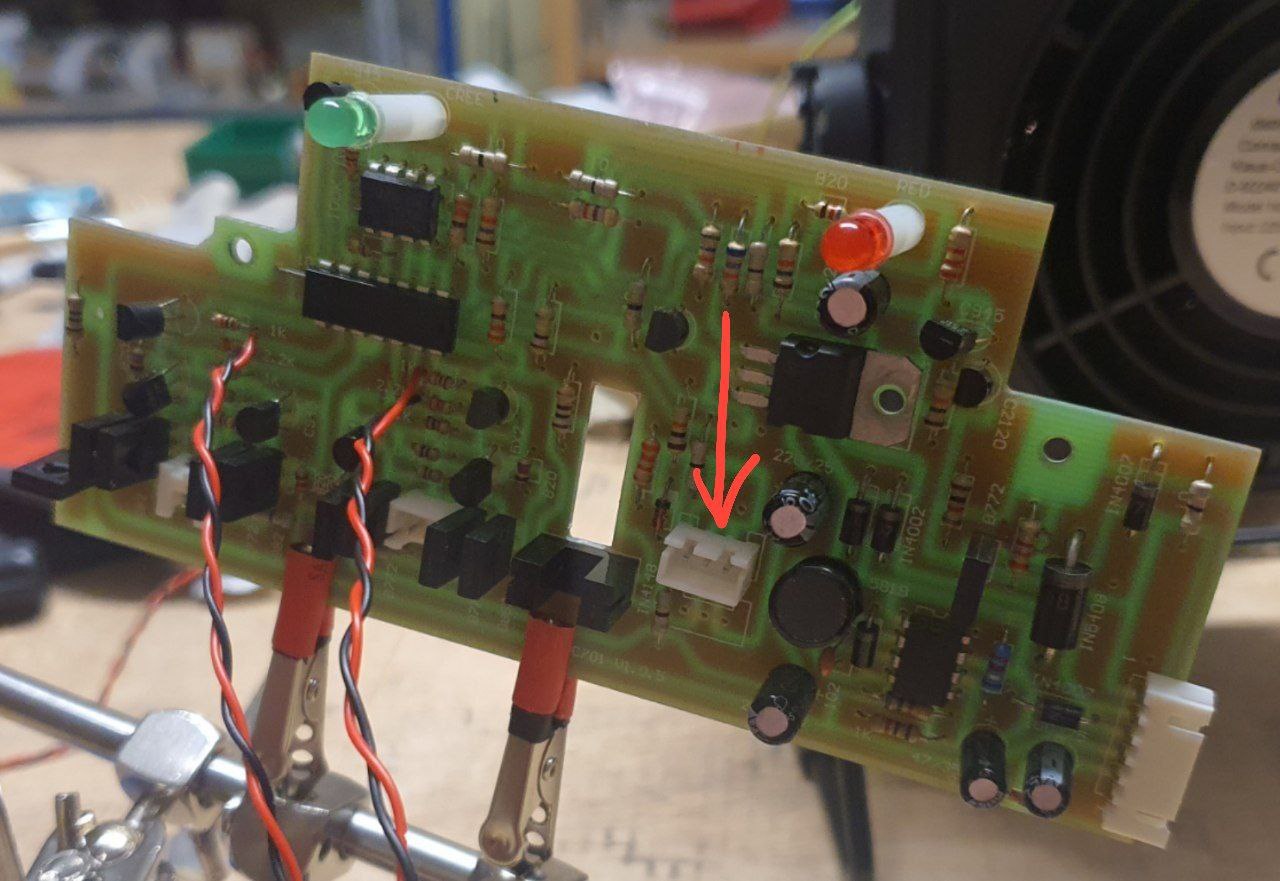
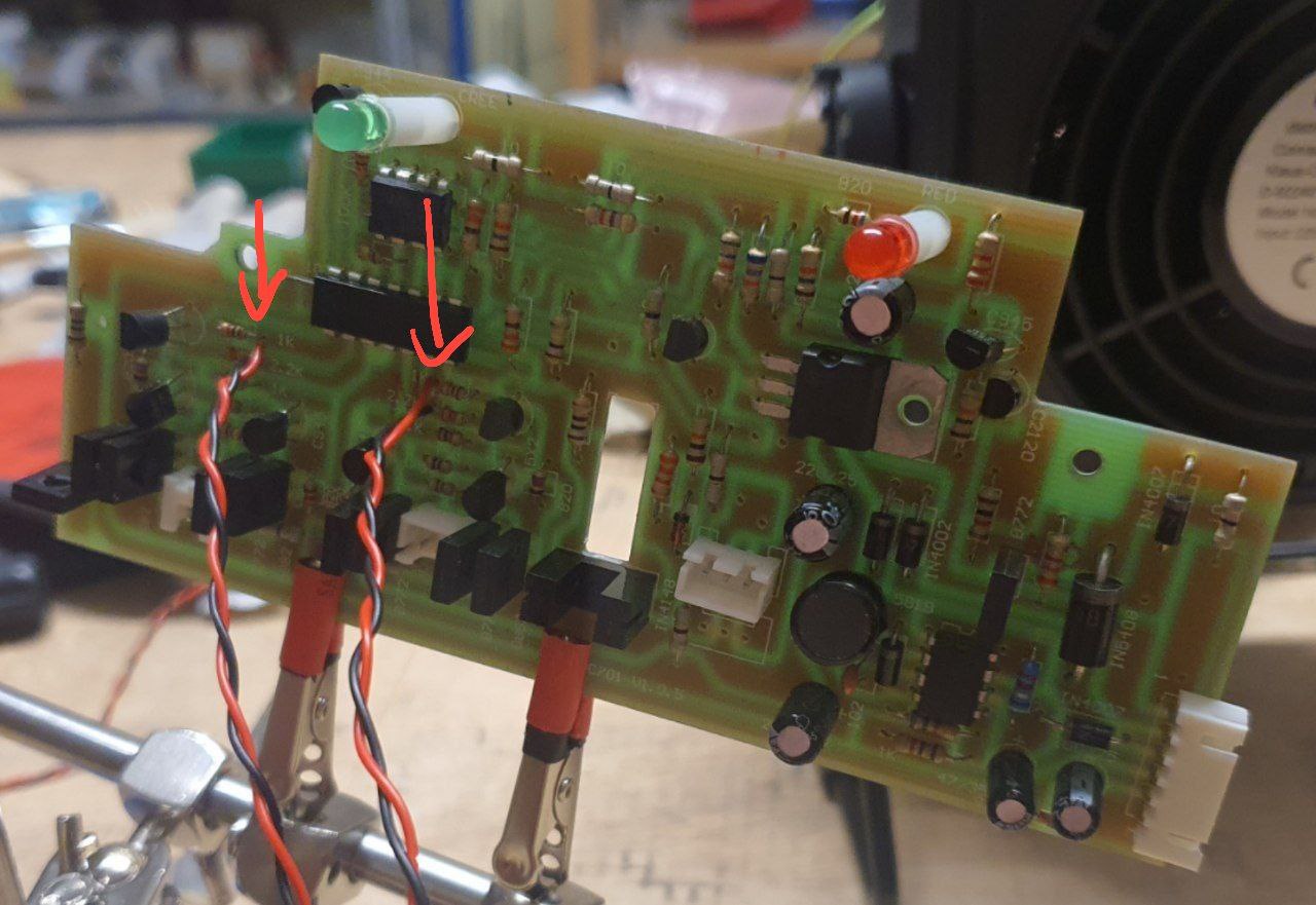
To use the microcontroller for driving the robot, I had to find a way to connect the ESP32’s GPIO-Pins to the input of the motor drivers.
Remembering what I’ve learned from the PCB-Analysis, I figured that the best way to approach this would be to replace the pins 8,9,12 and 13 of the main IC with my own GPIO signals.
My first idea was to cut off the corresponding legs of the main IC and solder the cables to the remaining holes. This turned out to be very hard, since reaching the little legs with even the smallest side-cutters I had was next to impossible, and unsoldering the whole chip would be pretty inconvenient.
That’s why I a look at the traces of the main IC’s pins again. I found some resistors which seemed to be the input points of the motor drivers and soldered my wires directly to them. To stop the old IC from interfering with my signals, I used a sharp knife to cut the PCB traces at its base.
Injection points for the left and right forward/backwards signals
Testing the connections
To test if everything worked as expected, I wrote a simple script for the ESP32 which turns the connected pins on and of for a certain amount of time. Running this script revealed that everything worked as expected. I could observe the wheels turning and stopping, which meant that my signal injection was a success. I found out that even using PDM-Signals to control the speed of each wheel worked almost flawlessly.
]]>Topan AVC701 PCB Analysis | Hacking a cleaning Robot2024-09-22T22:02:54+00:002024-09-22T22:02:54+00:00https://skyfighter64.github.io/robot/2024/09/22/Hacking-A-Cleaning-RobotIntroduction
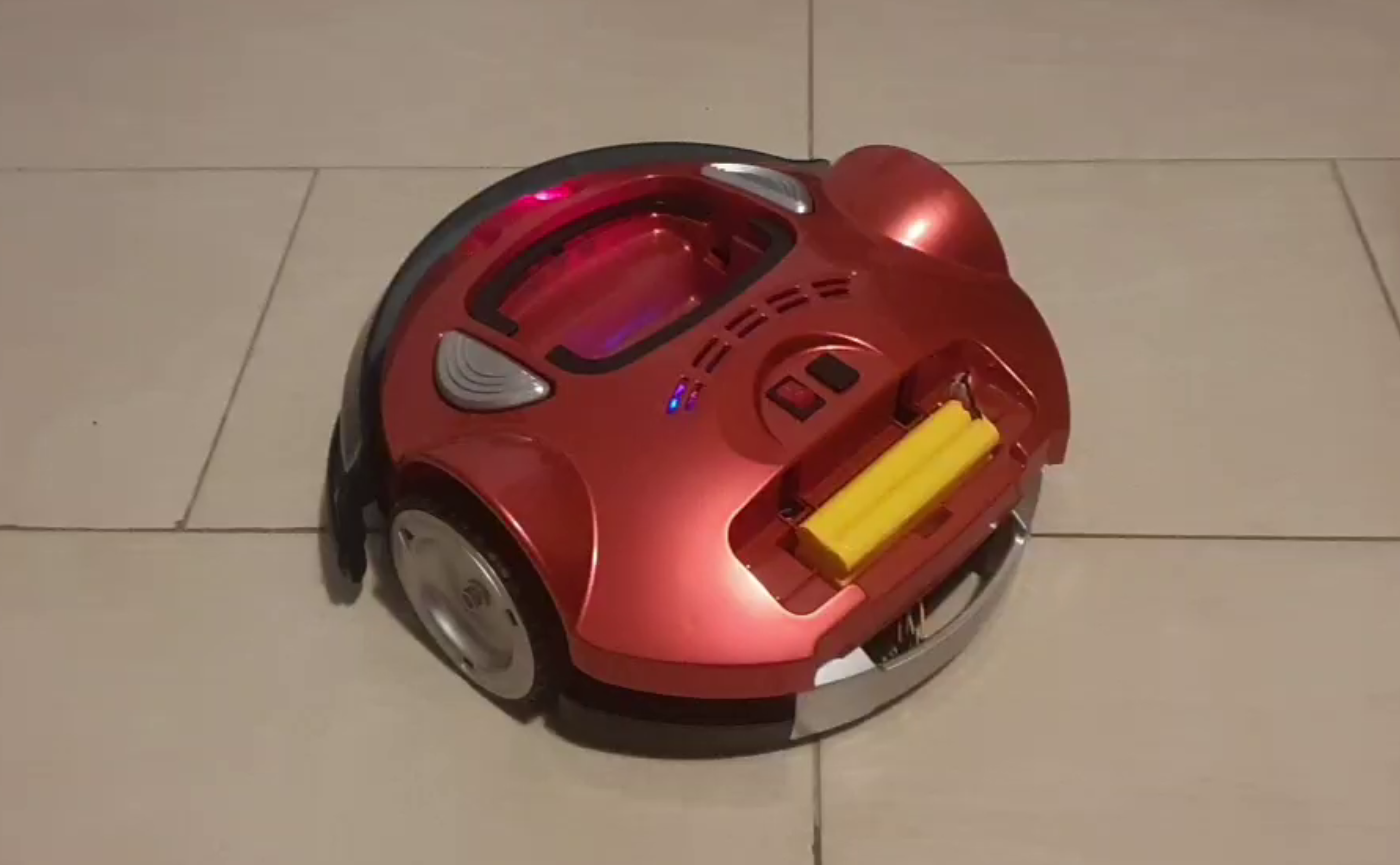
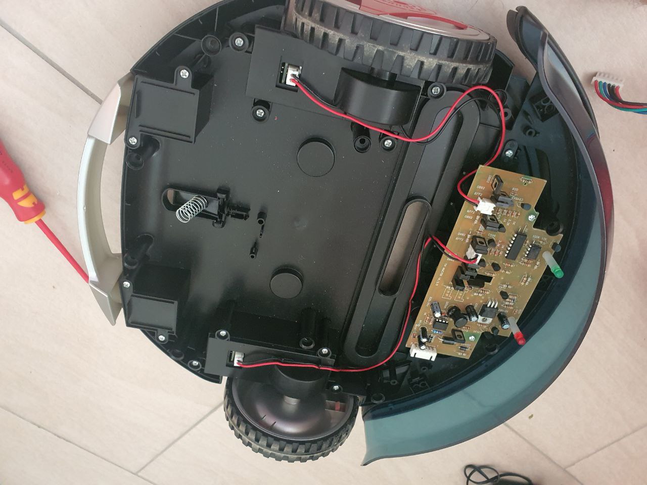
The other day I got my hands onto a “BRUNEAU TP-AVC701” or “Topan TP-AVC701” cleaning robot and wanted to make it drive autonomously using a Microcontroller. After opening it up and looking at the rather
simple PCB, I thought it might be possible to inject signals directly into it, eliminating the need for new motor controllers
and a battery charging circuit.
That’s why I analyzed the contents of the PCB and traced all copper lines and parts to its original purpose.
Rainer Rebhan also hacked this robot, if you don’t want to keep the old PCB is suggest checking out his website.
Robot Overview
The robot itself is rather simple. It drives around in fixed
patterns, reversing and turning away if it hits something with its front bumper.
It is turned on using a switch at the top and can be charged using an external 14.4V Power Supply.
The following images show the robot from the outside and inside:
As you can see, there is a lot of space for modifications and tinkering. Note that I already removed some unneeded parts like the vacuum motor.
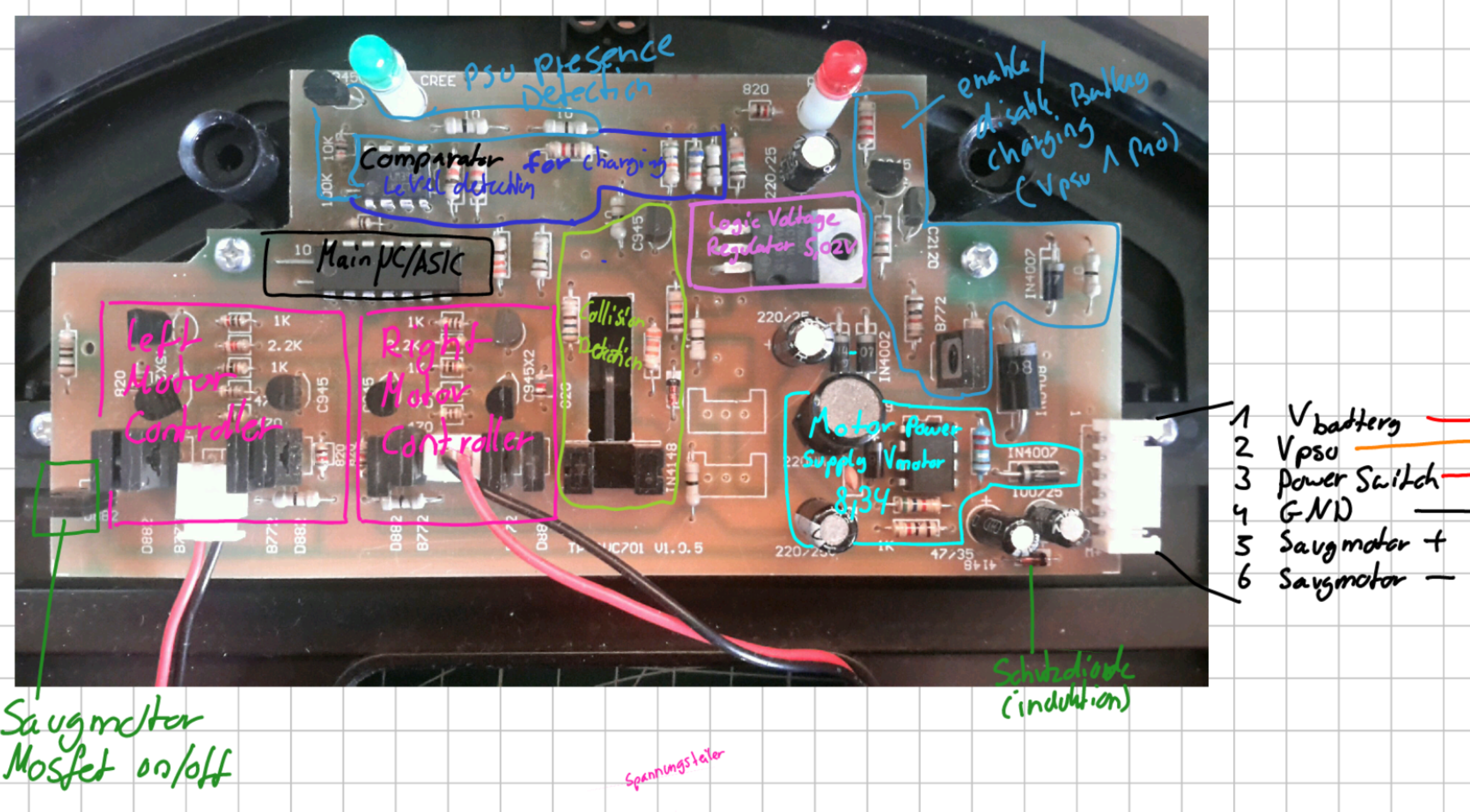
Main PCB Features
The default PCB already comes with a good set of features, namely:
Battery Charging/Discharging logic
Motor Driver for both wheel motors
On/Off control for the vacuum motor
Collision Detection using the front bumper
Two DC/DC Converters
PCB Sections
The following image shows the different purposes I determined for the different areas of the main PCB. Each feature is explained in more detail below.
6-Pin Connector
The 6 Pin JST connector on the right side connects the main PCB to two small daughterboards in the casing. These connect to the battery, PSU and ON/OFF switch. It also connects directly to the vacuum motor.
Pin
Purpose
1
V_battery (Positive battery terminal)
2
V_psu (Positive Power supply terminal)
3
Power Switch (ON: V_battery, OFF: NC)
4
Ground
5
Vacuum Motor +
6
Vacuum Motor -
Note that the Power Switch at Pin 3 is connected to V_battery if the switch is turned ON. This serves as the main power source for the robot when running. Connector Pin 1 on the other hand is always connected to the Battery and is used to charge the robot when a PSU is present.
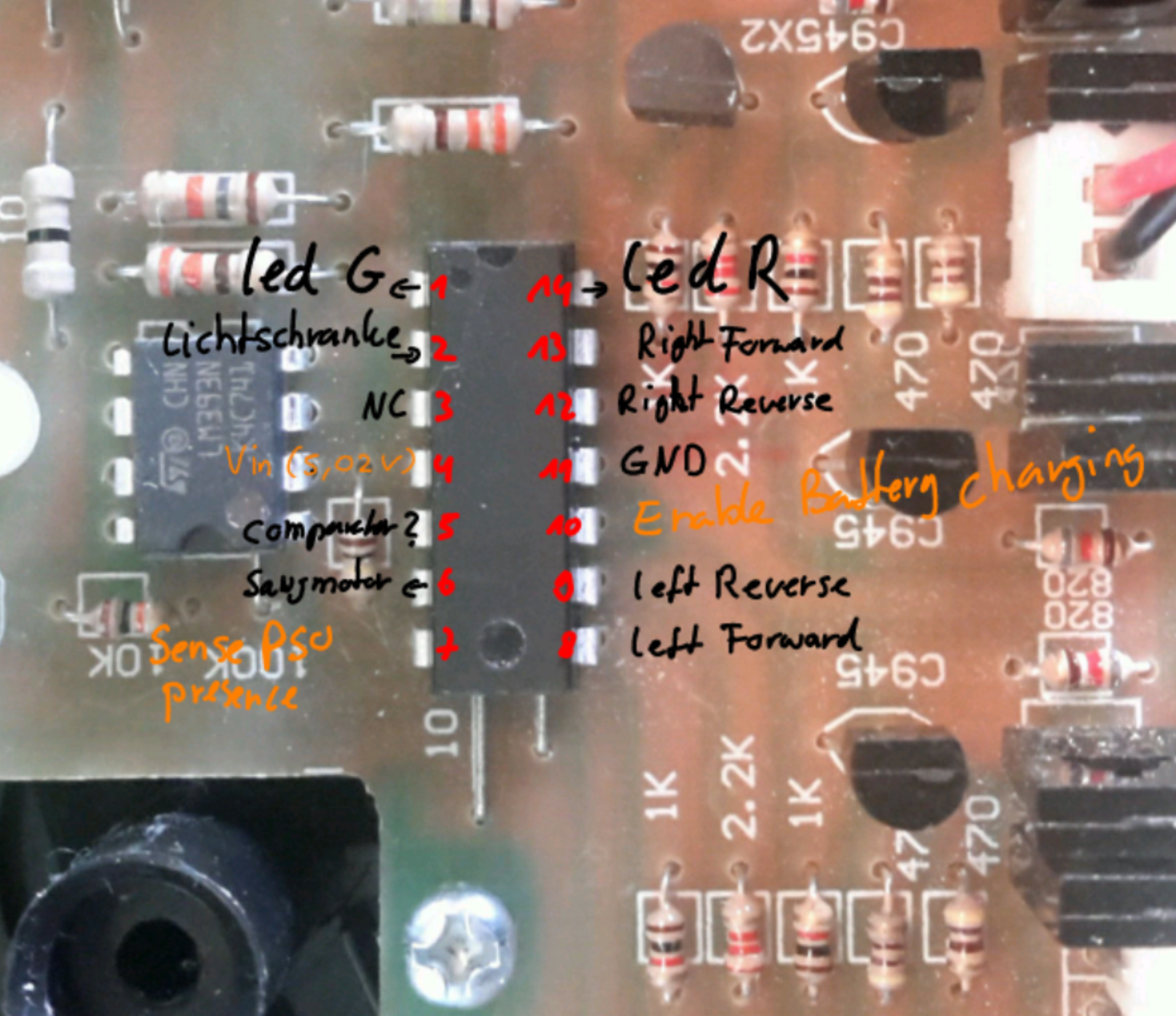
Main IC
The main IC seems to be either a microcontroller or (more likely) a custom made ASIC. It controls basically everything on the robot including:
Both driving Motor’s speed
Vacuum Motor ON/OFF
Battery charging
Blinky LEDs
Collision Detection
Picture of the main IC:
Pinout:
Mode
Purpose
Pin
Pin
Purpose
Mode
┌
─
\_/
─
┐
Output
Green LED
1
─
┤
0
├
─
14
Red LED
Output
Input
Light Barrier
2
─
┤
├
─
13
Right Wheel Forward
Output
NC
3
─
┤
├
─
12
Right Wheel Reverse
Output
V_logic (5V)
4
─
┤
├
─
11
Ground
Input
Comparator
5
─
┤
├
─
10
Battery Charging Enable
Output
Output
Vacuum Motor On/OFF
6
─
┤
├
─
9
Left Wheel Reverse
Output
Input
Sense PSU Presence
7
─
┤
├
─
8
Left Wheel Forward
Output
└
─
─
─
┘
Motor Drivers
There are two motor drivers, each consisting of a H-Bridge and some upstream logic.
The following pins from the main IC are used for driving:
Pin NR
Motor
Purpose
13
Right
Forward
12
Right
Reverse
9
Left
Reverse
8
Left
Forward
The previously mentioned extra logic makes sure that the robot does not try to
drive forward and reverse at the same time:
Pin 8 | 13 (Forward)
Pin 9 | 12 (Reverse)
Motor Driver Output
0
0
Stop
0
1
Reverse
1
0
Forward
1
1
Reverse
Charging Circuit
The Charging logic consists of a Voltage Sensing Circuit and a Charging Activation Circuit controlled by the main IC.
Using its two internal Comparators, the lm393N checks the reduced PSU/Battery Voltage max(V_battery, V_PSU) and the Motor Voltage V_motor against the 5V logic Voltage V_logic and outputs a logic 1 to the main IC if either of the Voltages is greater than V_logic.
Note:
The exact purpose of the Comparator is currently unclear to me. Unfortunately, I don’t have the original PSU anymore and therefore cannot confirm my theories.
The measurements using another Power Supply did not replicate my expected behavior so take this section with a grain of salt.
Depending on the logic signal of the comparator (and maybe something else), the main IC enables the battery charging logic, which checks if a PSU is present, and if so, connects V_battery and V_PSU together using a MOSFET.
Light Barrier
The light barrier is used for detecting collisions using the front bumper. If the robot bumps into something while driving, a plastic piece blocks the light barrier and the robot stops, reverses and turns around.
Power Distribution
The PCB has two main Power Sources: The Battery and an external Power Supply.
Depending on the power source used, two different DC/DC Converters create the voltages needed by the components and motors.
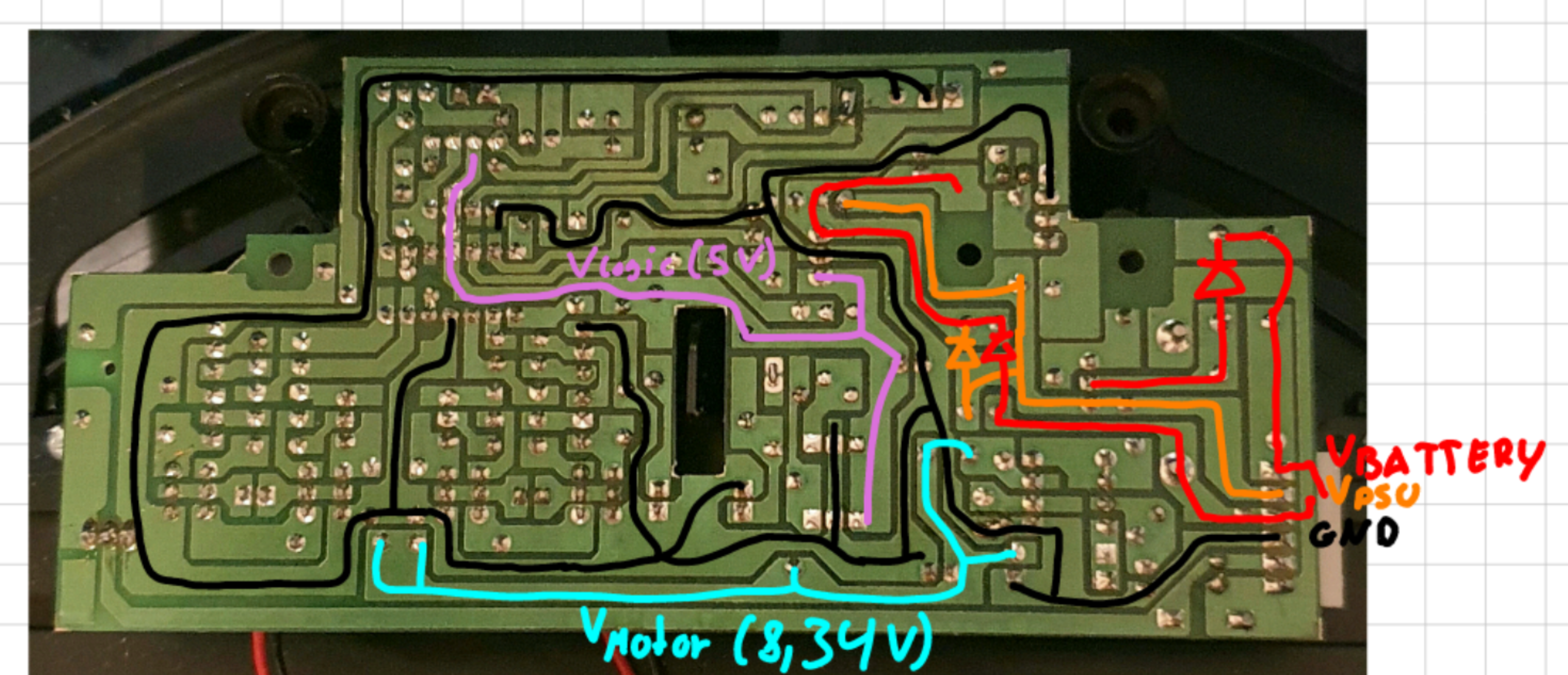
Here is a quick overview over the different power rails:
Note that the Image is mirrored to make it easier matching the components on the other side.
L7805CV Voltage Regulator
This Voltage regulator receives the variable voltage from either the Battery or the Power Supply (if connected) and regulates it down to a constant 5.02V. It is used to power the main IC and the light barrier.
According to its data sheet, it has all kinds of protection circuits and can provide up to 1.5A of current (although this requires an additional heat sink).
34063AP1 Buck/Boost Converter
This is the second DC/DC Converter on this board. Its purpose is to provide 8.34V to the motor controller of both driving motors.
It only delivers power when the robot is in battery powered mode and the switch is turned on.
Vacuum Motor
The Vacuum motor is using the battery voltage V_Switch for power. It can be switched ON/OFF by the main IC using a MOSFET. For my purposes it was not needed anymore, which is why I removed it.


 Note that the Image is mirrored to make it easier matching the components on the other side.